Define zener diode. What is Zener Diode? 2019-12-28
Diode

They are also used as large-volume, ionizing-radiation detectors and as. This sudden increase in electric current may permanently destroys the normal diode. When a high reverse voltage is applied across the junction, there will be very strong electric field at the junction. The current flowing through the device shows its maximal increase up to circuit permissible value. They slowly lost market share beginning in the late 1940s due to technology and then to semiconductor diodes during the 1960s.
Next
What does Zener diode mean?

Step 2: Small voltage applied to the tunnel diode When a small voltage is applied to the tunnel diode which is less than the built-in voltage of the depletion layer, no forward current flows through the junction. The filament itself may be the cathode, or more commonly as shown here used to heat a separate metal tube which serves as the cathode. The metal side is the pointed end of a small diameter wire that is in contact with the semiconductor crystal. Construction of Zener diode The figure below, represents the diffused structure of a Zener diode: Here, N and P substrate are diffused together. When a mobile electron recombines with a hole, both hole and electron vanish, leaving behind an immobile positively charged donor dopant on the N side and negatively charged acceptor dopant on the P side. The difference between the avalanche diode which has a reverse breakdown above about 6.
Next
Zener diode dictionary definition

Before the development of silicon power rectifier diodes, and later was used. The 1N34A is another example of a crystal diode. When the voltage is less than 0. The only practical difference between the two types is they have temperature coefficients of opposite polarities. Therefore, zener diodes allow more electric current than the normal p-n junction diodes. The electrons present in the depletion region utilize that energy and get separated with the parent atom. This is typically an undesired effect, so most semiconductors are packaged in light blocking material.
Next
What is a Diode?

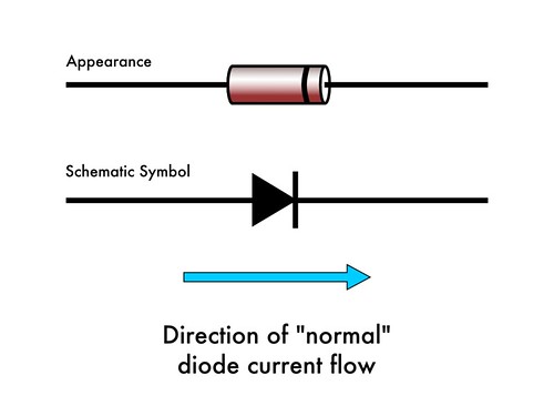
But an avalanche diode carefully manufactured to operate in breakdown region withstand the high current flowing through it. The junction region is covered with a layer of silicon dioxide SiO 2. The depletion layer of tunnel diode is very small. Silicon and germanium are quite different in their ability to convert to electron showers. The value of this current is given in the data sheet for D. Diodes allow current to flow in one direction only.
Next
Zener diode

For example, a diode with a Zener breakdown voltage of 3. The portion of the curve in which current decreases as the voltage increases is the negative resistance region of the tunnel diode. The operating temperature of the cathode causes it to release into the vacuum, a process called. Thus, is used in the construction of zener diode. The reverse saturation current, I S, is not constant for a given device, but varies with temperature; usually more significantly than V T, so that V D typically decreases as T increases. The name zener diode was named after the American physicist Clarance Melvin Zener who discovered the zener effect.
Next
Tunnel Diode

This allows the diode to operate at signal frequencies, at the expense of a higher forward voltage drop. All semiconductors are subject to optical generation. There is a minimum zener current for which the stabilisation of the voltage is effective and the zener current must stay above this value operating under load within its breakdown region at all times. Thus, tunnel current starts flowing with a small application of voltage. For longer-range about a centimetre particles, they need a very large depletion depth and large area. The word diode, however, as well as , , , , were already in use as terms of. Also, following the end of forward conduction in any diode, there is reverse current for a short time.
Next
What does Zener diode mean?

The stabilised output voltage is always selected to be the same as the breakdown voltage V Z of the diode. The operation of a zener diode is alike normal diode in forward biased mode. With the increase in reverse potential, a strong electric field is generated by the depletion region. Usually, clipping is done to protect the voltage sensitive devices from overvoltages. This can be done by placing the two Zener Diodes in series with the resistance. To overcome this barrier, we need to apply sufficient voltage.
Next
Diode

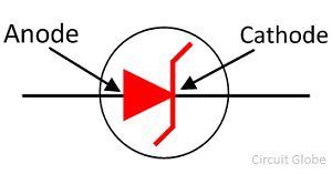
The end of the diode with the Z on its side is the cathode. Because of this overlapping, the conduction band electrons at n-side and valence band holes at p-side are nearly at the same energy level. However, this is temperature dependent, and at sufficiently high temperatures, a substantial amount of reverse current can be observed mA or more. This is an intentional distortion of a signal. The temperature coefficient is approximately constant for temperatures above about 20. For Meter Protection — The Zener diode is generally used in multimeters for controlling the movement of the meter against accidental overloads. Or am I missing something? Remember the names of the two diode connections? Because of energy loss fluctuations, accurate measurement of the energy deposited is of less use.
Next
Zener

In detector and mixer applications, the current can be estimated by a Taylor's series. This region is particularly important for power diodes. Using the zener regulator circuit above calculate: a. This will create a small forward bias tunnel current. This is called the phenomenon.
Next
Zener

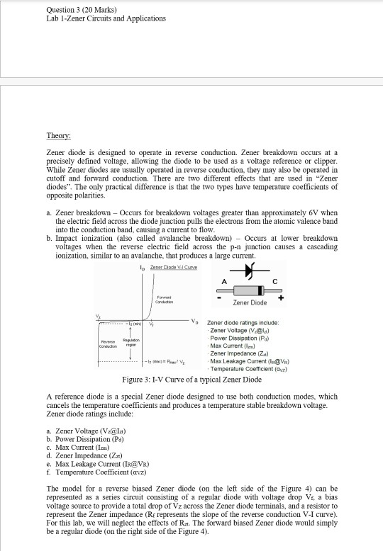
In 1973 Leo Esaki received the Nobel Prize in physics for discovering the electron tunneling effect used in these diodes. The audio is then extracted from the rectified carrier wave using a simple and fed into an audio amplifier or , which generates sound waves. Other uses for semiconductor diodes include the sensing of temperature, and computing analog see. From the Shockley ideal diode equation given above, it might appear that the voltage has a positive temperature coefficient at a constant current , but usually the variation of the term is more significant than the variation in the thermal voltage term. When connected in parallel with a variable voltage source so that it is reverse biased, a Zener diode conducts when the voltage reaches the diode's reverse breakdown voltage. The graph of the Zener breakdown is not exactly vertical shown above which shows that the Zener diode has resistance.
Next


