Free cad tutorial. Basic modeling tutorial 2019-12-22
FreeCAD Tutorial Part 1: The Part Workbench
At this point, let's save our document. You should see in the 3D view, the 3 axes X, Y, Z in red, green and blue. Now select rectangle tool and place a rectangle on the rear face of the part in a similar fashion as shown below. Click on , enter a value of 50 mm. Select the Create pocket from selected sketch option. The rectangle drawing command is still active. They will be created during assembly designing process - there is no graphical import tool for files containing feature tree yet.
Next
FreeCAD Beginner Tutorial & How
A view like this appears: Hold and drag the cones along the axes or the spheres to move the body in all directions. In the panel on the left side Pad parameters appeared. At this point if we were to simply Pocket this sketch, the resulting hole would be perpendicular to the sloped face that it is mapped to, and this is not what we want. In fact, it has claimed Sketch, since it is based on it; clicking on the arrow or plus sign in front of Pad to expand it will reveal the Sketch underneath, which was automatically made hidden its label is grayed out. Before we continue, let's take the opportunity to rename the Body.
Next
FreeCAD Tutorial

There is an easy way to do this. Vector 0, 1, 0 , 90 App. Both operations are called features. You can also add or delete these constraints manually. See the for screen captures showing the two expanded modes.
Next
FreeCAD Beginner Tutorial & How

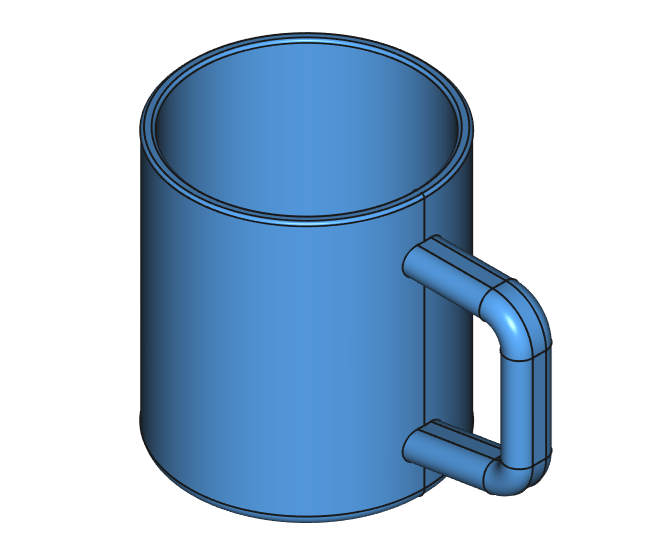
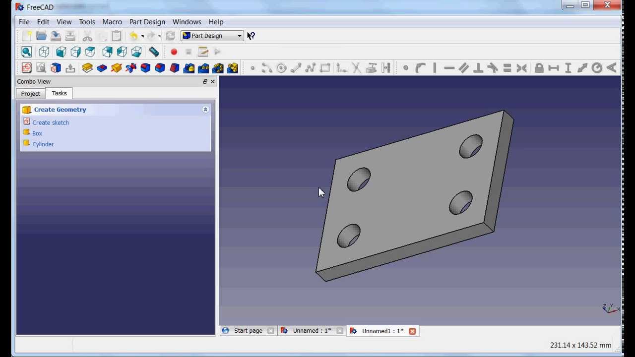
If you can create this file you have successfully mastered this tutorial and are good to go for your own creations now. Visit and for lists of tutorials hosted on external sites. Now orbiting around to the back face, or alternatively double clicking on the active sketch in the Model tree view, you will see the two external geometry lines that we provided from the front of the model. Do the same for the horizontal length of the sloped line with another 50 mm vertical distance constraint. The same window appears as before and enter 200 in the Length field. New users should watch videos for versions 0.
Next
FreeCAD tutorial
Before we move to dimensioning, we still need to convert some edge of the rectangle to the sketch. Quantity str angle +' deg' Rename objects to Conrod, Piston and drivingskt respectively. In this way, we already know how to add a pad operation and how to edit it. You should get pretty much this: Note the small red lines above and beside the segments you have drawn: these are horizontal and vertical constraints. Make a rectangle and using the coincident constraint, do the following. As a result, drawing the next four holes will be easier. Using the arrows you can vary the position and angles of the part.
Next
Getting Started with FreeCAD
It also shows how to do some assemblies and drawings. This landmark is fixed and immutable, it is either the view that rotates or the object that rotates in this space. A video of these steps of the tutorial is here: Your model will have some extra lines on it compared to the images in this tutorial. Then we dimension one circle. Now we can dimension the rectangle.
Next
FreeCAD Tutorial Part 1: The Part Workbench

If you had Auto constraints on, some of these constraints will have been applied automatically, if not, do the following. Although they may be considered obsolete, they are included here for reference as the information they contain may still be useful for intermediate and advanced users. Now in sketch edit mode, we will orbit back around to the front so we can see two perpendicular edges of the Pad we made in the last operation. Absolute beginners are advised to avoid these videos until they have a better understanding of modelling techniques. In the Model tab, in the left pane, we must select the last operation. The Mirror feature works in this way because the base feature of our model was Padded both ways from the horizontal plane in the first operation with the base sketch.
Next
FreeCAD Tutorial
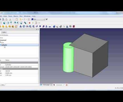
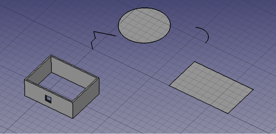
Then click on one face surface of the 3D model and continue with the next sketch. In this way, we get a pocket from the sketch. I think that for the beginning this information is enough and we can go further. Vector 0, 37, 0 App. Also this branch is at the moment not usably. In order to easily indicate the edges, you can switch to the wireframe view. You have two parts: a box with a hole and a cylinder.
Next
Category:Tutorials
Some more advanced instructions include how to do logo design, metal bending, and assembly. A useful source of video tutorials is. After that, you turn this sketch in a new 3D shape, etc. Once you have the view of the front, click on the sloped face with your mouse to select the face we will use for the next sketch. One thing to remember: in Inventor navigation mode, Ctrl + click does not work for multiple selection.
Next
FreeCAD Tutorial Part 1: The Part Workbench

Then select the symmetry constraint. It is now very easy to center the circle! An easier way is to use the Fit the whole content on the screen. We get: For the edges marked in the figure below, add a chamfer of 1 mm. . We proceeded in two stages to create the sketch, but we could also have traced the profile completely before constraining it fully. Mostly in German, some videos in English.
Next