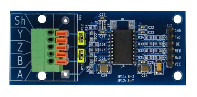
Arduino rs485 shield. ahintz.com: RS232/RS485 Shield for Arduino: Computers & Accessories 2019-12-28
Arduino RS485 Shield (RJ45, bus

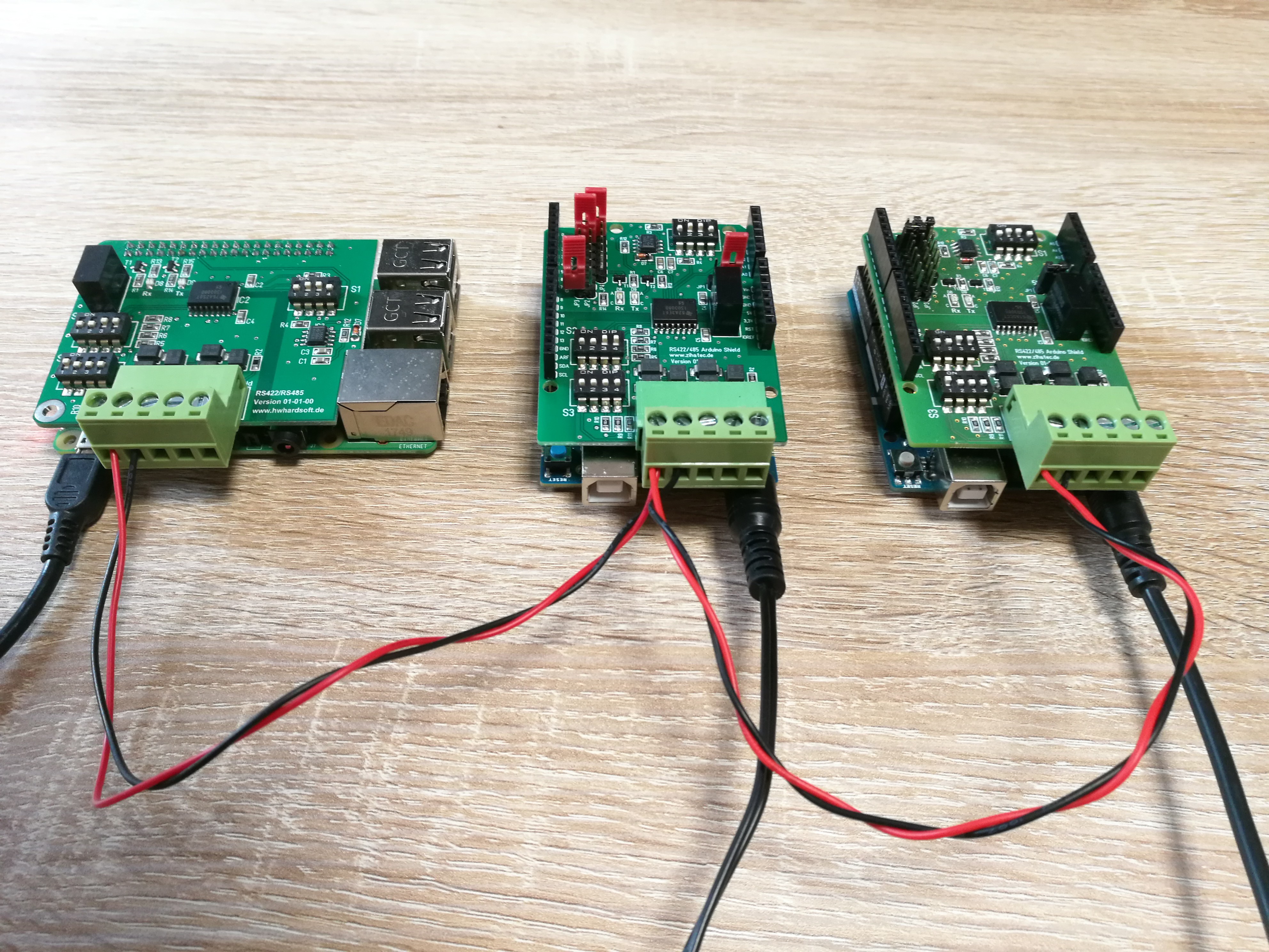
It would also be nice to see a jumper selectable terminating resistor for those really long runs. Because one is high and the other low to represent a 0 and the other way around to represent a 1. The second 'pain', is the error on the Schematic. Initially, I planned to just transfer data bytes. Every device is connected to the 2 wires Picture 1.
Next
Arduino MKR 485 Shield

In you can also see it plotted in the Scope Picture 3. Imagine an art installation with a sensor at the door which triggers movements and sounds all over the room. Function 5 write single coil is not implemented so I'm using a whole register and function 16 to set the onboard Led on the Atmega328P. The person was using a different shield but they were running into the same issue due to Atmega32U4's software serial limitation. You literally have to take the shield off to program the Arduino and it becomes such a hassle when you are debugging software and not only that, you are making the connector terminals wider.
Next
RS

If you doné have a socket left in your room you use a power strip as well don't you? I tried every possible jumper combination on this shield and it doesn't work. There is a switch which allows to switch between hardware serial pin 0 and 1 and software serial pin 2 and 3. To do that we need to use a Flip-Flop. I have two of these running in the field. The commands will arrive as text followed by enter. However I still need the slave far from the master.
Next
ahintz.com: RS232/RS485 Shield for Arduino: Computers & Accessories
.jpg)
If you want to have 2 Arduinos talking this board would work fine as is. You basically end up with things fighting over the hardware line. Because the nodes can be bus-powered, this saves you a lot of wiring and hassle. Had a couple minor problems. Your output looks like the Mega ran setup twice. It won't work unless somewhere else on the rs485 bus it is biased so the other state is the default. The transmitter should be enabled for both 0 and 1 bits.
Next
RS232/485 Shield For Arduino

Check below if you need to add the connector. So consider soldering it all on a proto board. Picture 1 and the Video show the connected and powered up project. Why did you make it? If anyone has any questions how to achieve this, I will post a instructional download so everyone can do this with pictures. If the injector uses the right pinout probably and supplies 24V or less, you should be fine. It also allows multiple boards to be connected easily to the same 2 wires. Heck, I could populate it as an arduino with 485 built-in! This also allows for programming older Arduino's without taking the shield off.
Next
RS485 Shield For Arduino

This board uses the hardware serial pins 0,1 , not software serial. And on Picture 5 you can see the complete Visuino diagram for the. The : also needs to be installed. Additionally, the shield has a wide-input voltage regulator on board, which allows you to power the shield and Arduino remotely in a way similar to. You can also program the Arduino while the shield is on the Arduino, so you don't have to keep taking it off and on.
Next
RS485 Shield

I have on more than one occasion had equipment that refuses to work without it. I also expect that the appropriate product will conatain the documentation or the seler can provide the links where to get it Looking forward to hearing from you quickly. I already tested this and works great now. On Picture 4 you can see the complete diagram for the. Code samples in the guide are released into the public domain.
Next
ahintz.com: RS232/RS485 Shield for Arduino: Computers & Accessories

At least one mentioned below uses a retriggerable timer circuit so specific code to control the transmit enable line isn't needed. Not a big deal, but wasted a little time until I figured this out. This only needs limited functionality for our purposes, We all looking to create a controller that will start recording and stop recording and provide the feed back signal so we know if we are recording before a launch. I did get communication between two Uno boards - after I connected their grounds together, as most info mentions. If you connect to the with Serial Terminal or you will see the position of the potentiometer displayed in text form Picture 2.
Next
RS485

There are many ways to reroute pins from a shield. I bought this to connect to a Love Controls temperature controller ModBus interface and had it up and running within less than an hour. I'm really new to serial com, and it took me a week of struggling to make it work - but this shield will work. If you turn the Potentiometer the values will change. I was hoping to see some response from your device.
Next
RS485 Serial Communication Between Arduino Mega and Arduino Nano With Visuino: 20 Steps (with Pictures)

Does anyone know of a way I can rig it up so I can wire the board up to not do this? Sometimes we need to connect Arduino boards located far away from each other. Please tell me there is another version of this coming out, why doesn't this thing have the capability of on-board programming like the rest of the shields do? So I've wired it up, written a simple test sketch and. I tried powering the slave up using the 5V from the master to the Vin and it worked! The first perf-board test version of this shield took 3 hours to manually assemble. It can also be used in the final application, if your application has space and budget for full-sized Arduino's with shields. Low latency delays makes the implementation non-standard but practically it works with all major modbus master implementations.
Next


.jpg)


